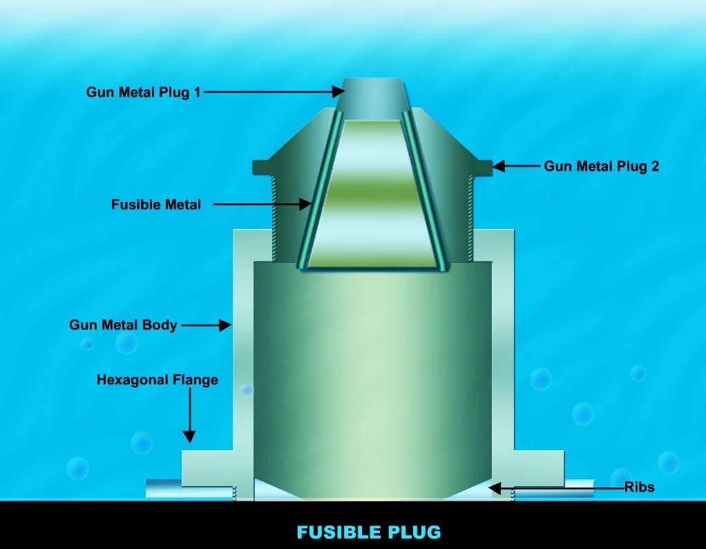
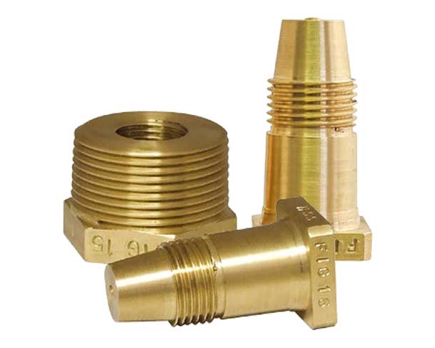
Fusible Plug is a fitting used in Steam Boilers to enhance the safety during operation. It’s working depends upon the water level in the Boiler shell.
Fusible Plug in Boilers
Fusible plugs are safety devices used in steam boilers to prevent overheating and explosions. They are typically threaded cylinders with a low-melting-point seal that melts when the temperature reaches a predetermined level. This allows steam or hot gases to escape, preventing excessive pressure buildup and potential explosions.
The main function of a fusible plug is to enhance safety during boiler operation. Its working principle depends on the water level in the boiler shell. If the water level drops too low, the fusible plug is exposed to high temperatures, causing the seal to melt and allowing the steam or hot gases to escape. This helps prevent the formation of excessive pressure and potential boiler explosions
Fusible plug material in boiler
The fusible plug material in a boiler is typically tin, which has a melting point of 232°C (450°F). The plug is made of a brass, bronze, or gunmetal body with a tapered hole drilled completely through its length. The hole is sealed with a slug of tin, which melts when the boiler overheats. This allows steam to escape from the boiler, which prevents it from exploding.
Other materials that can be used for the fusible alloy in a boiler include lead, bismuth, and cadmium. These materials have melting points that are lower than tin, so they will melt at a lower temperature. This can be helpful in boilers that are exposed to very high temperatures.
The fusible plug is an important safety feature in boilers. It helps to prevent catastrophic accidents that can cause serious injury or death. Boiler operators should regularly inspect the fusible plug to make sure that it is in good condition and that the fusible alloy is not corroded or damaged.
Here are some additional facts about fusible plugs in boilers:
- The fusible plug is typically located on the crown sheet of the boiler, which is the highest point in the boiler.
- The fusible plug is usually threaded so that it can be easily replaced.
- Fusible plugs should be replaced annually, or more often if the boiler is used in harsh conditions.
Fusible Plug Function
In a smoke tube steam boiler, it is fitted on the front tube sheet, just above the tubes (used for flue gas flow) arrangement but below the perforated feed line inside the shell.

What happens is that during steam boiler operation, the feed pumps supply water for steam conversion in the Boiler shell on the basis of the signal sent to it by the electrical panel.
And electrical panel receives this signal from the mobrey (automatic water level controller) based on the fluctuating water levels due to continuous steam generation.

So, if anyhow, this loop of supplying water to the Steam boiler does not work (because of any fault) during Boiler operation then after some time the water level in the Boiler shell will first go down the low water level, then the perforated line.
Other Products
Now because of the reduced quantity of water in the Steam Boiler shell, the steam volume in the shell rises and because of continuous combustion in the furnace the temp of this steam goes up and it gets superheated.
When the water level goes below the fusible plug, the lead present inside the Plug gets melted because of super-heated steam and now the water from the boiler shell comes out and wets the flue gases and even disrupting the combustion thereby protecting the Steam Boiler from any mishap that may have happened otherwise.
Buy Bronze Boiler Fusible – Plug
We, at Thermodyne, supply Smoke Tube Steam Boilers with all such desired protections to avoid a tension-free and reliable operation of the Steam Boiler.
Fusible Plug-Related FAQs
What will happen if a fusible plug is not used in the boiler?
When the steam temperature reaches the melting point of the fusible plug, the plug melts and sends the steam out through the plug hole. This escaped steam avoided overpressure in the steam boiler vessel which eliminated the risk of bursts in steam boilers.
What temperature does a fusible plug in a boiler melt at?
Fire-activated plugs are made up of pure tin material and feature a melting point of 232 °C.
Where are the fusible plug-in small boilers located?
Steam Boiler Fusible plug is a pressure safety valve (PSV) that defends the boiler from failure due to high pressure. The fusible plug is located on the top surface of the steam boilers.
Boiler Resources Page Here
- Boiler Losses That Eat Away Your Profits
- Dissolved Gases in Feed Water and Its Effect
- Pressure Reduction System
- How to minimize the Blowdown Losses
Fusible plug material in boilerfusible plug material in boiler
To calculate the power required for your ID fan motor, you will need to know the following information:
- The volume of air that the fan needs to move (in cubic meters per hour)
- The pressure difference that the fan needs to overcome (in millimeters of water column)
- The efficiency of the fan and drive system (typically around 65%)
Once you have this information, you can use the following formula to calculate the power required:
Power = (Volume of air * Pressure difference) / Efficiency
For example, if your fan needs to move 100 cubic meters of air per hour and the pressure difference is 100 millimeters of water column, the power required would be:
Power = (100 m3/h * 100 mmWC) / 0.65 = 1,538 watts
Online Induced Draft (ID) Fan Motor Power Calculator:
ID Fan Motor Power Calculator:
Induced Draft (ID) Fan is used to draw the flue gases from the system generated from the combustion of fuel. The motor power required for its working depends upon the following factors:-
- ID Fan Capacity – Quantity of flue gases drawn from the system measured in (m^3/Hr).
- ID Fan Head – Amount of pressure required by flue gases to overcome the friction or bending losses as it passes through the system, measured in (mm WC).
Flue gas temperature at the inlet of Induced Draft Fan.
Thermodyne ID Fan Motor Power Calculator:
See Also: Boiler Blowdown Calculation Formula & Calculator
This is just a general calculation and the actual power required may vary depending on the specific fan and drive system. It is always best to consult the manufacturer’s specifications for the exact power requirements.
Here are some additional factors that can affect the power required for an ID fan motor:
- The speed of the fan
- The size of the fan
- The type of fan (axial, centrifugal, etc.)
- The materials used in the fan
- The environment in which the fan is operating (temperature, humidity, etc.)
It is important to consider all of these factors when selecting an ID fan motor to ensure that it has the capacity to meet the required airflow and pressure requirements.
Calculate the Power Required for Your ID Fan Motor
Fusible Plug-Related FAQs
What will happen if a fusible plug is not used in the boiler?
When the steam temperature reaches the melting point of the fusible plug, the plug melts and sends the steam out through the plug hole. This escaped steam avoided overpressure in the steam boiler vessel which eliminated the risk of bursts in steam boilers.
What temperature does a fusible plug in a boiler melt at?
Fire-activated plugs are made up of pure tin material and feature a melting point of 232 °C.
Where are the fusible plug-in small boilers located?
Steam Boiler Fusible plug is a pressure safety valve (PSV) that defends the boiler from failure due to high pressure. The fusible plug is located on the top surface of the steam boilers.
An ID fan is a type of fan that is used to move air or gas inside a boiler. It is typically located in the furnace and is used to draw flue gases out of the boiler and into the stack
The formula for calculating ID fan power is:
Power = (Flow Rate x Head x Efficiency) / 1000
Where:
Flow Rate is the volume of air or gas that is being moved in cubic meters per hour (m3/hr)
The head is the pressure difference between the inlet and outlet of the fan in millimeters of water column (mmWC)
Efficiency is the percentage of the input power that is used to move the air or gas
What are the factors that affect ID fan power? The factors that affect ID fan power include:
The volume of air or gas that is being moved
The pressure difference between the inlet and outlet of the fan
The efficiency of the fan
The speed of the fan
The density of the air or gas
The volume of air or gas that is being moved
The pressure difference between the inlet and outlet of the fan
The efficiency of the fan
The speed of the fan
The density of the air or gas
The volume of air or gas that is being moved by an ID fan can be calculated using the following formula:
Flow Rate = (Area x Velocity) / 2
Where:
The area is the cross-sectional area of the fan in square meters (m2)
Velocity is the speed of the air or gas in meters per second (m/s)
The pressure difference between the inlet and outlet of an ID fan can be calculated using the following formula:
Head = (Density x Gravity x Height) / 2
Where:
Density is the density of the air or gas in kilograms per cubic meter (kg/m3)
Gravity is the acceleration due to gravity in meters per second squared (m/s2)
Height is the height difference between the inlet and outlet of the fan in meters (m)
The efficiency of an ID fan can be improved by:
Using a fan with a higher efficiency rating
Cleaning the fan regularly to remove dust and debris
Lubricating the fan bearings regularly
Adjusting the fan speed to match the load
There are two main types of ID fans: centrifugal fans and axial fans.
Centrifugal fans work by using centrifugal force to move air or gas. They are typically used for high-pressure applications.
Axial fans work by using the fan blades to move air or gas in a straight line. They are typically used for low-pressure applications.
ID fans have several advantages, including:
They can be used to move a large volume of air or gas
They are relatively efficient
They are relatively easy to maintain
ID fans have several disadvantages, including:
They can be noisy
They can be expensive
They can be difficult to install
Cleaning the fan regularly to remove dust and debris
Lubricating the fan bearings regularly
Adjusting the fan speed to match the load


